Skip to content

Ref Ct Connection Diagram Principle Ct Connections For The S

Principle CT connections for the first solution | Download Scientific

Ht line ct pt with ht meter connection diagram|| ct/pt to transformer Ref relay wiring diagram Fault restricted relay principle generators

Principle CT connections for the first solution | Download Scientific

Wiring diagram of current transformer... Principle ct connections for the second solution Restricted earth fault relay connection diagram 35+ pages explanation

High impedance protection ct connection for 5 ct arrangement

How to connect ct & pt to switchgear connection diagramHyderabad institute of electrical engineers: connections of ct Principle ct connections for the first solutionConnections principle solution.

High impedance protection ct connection for various ct arrangementImpedance arrangement Digital ammeter wiring with current transformerSignal transformer wiring diagram.

Digital Ammeter Wiring With Current Transformer - CT Coil

Can i use multiple current transformers on the same phase? : ekm

Fault earth restricted protection transformer current over relay ref backup circuit phase differential primary power substation path secondary electrical4u relaysFault relay earth restricted ct Current transformer installation for three phase power supply- ct coilWiring metering 9s.

Ref relay connection diagramErfolgreich nicht zugänglich blutbefleckt single phase electric meter 11kv ht metering connection with ct ptDigital ammeter wiring with current transformer.

Principle CT connections for the second solution | Download Scientific

Fault restricted ansi transformer

What is restricted earth fault relay 5 ct explanationFault earth protection restricted relay 64r connection transformer electrical4u ground working breaker Ac 3 phase 4 wire static kwh meter & ct wiring diagramRestricted earth fault protection system.

Ct connection diagram downloadFault earth protection restricted star relay neutral diagram transformer side wiring circuit system working connected explanation source protected shown below Current wiring ammeter digital ct transformer diagram circuit coil meter switch electrical electric power ampere generator panel energy article changeoverElectrical systems: july 2012.

Signal Transformer Wiring Diagram

Restricted earth fault relay connection diagram 35+ pages explanation

Restricted earth fault protection of transformer[diagram] wiring diagram kwh meter 3 phase Ct cores secondary circuit connection diagramCt connect switchgear.

Fault restricted relay transformer differential combined standby bined calculation eepCt vt connection pt electrical measuring burden main Restricted earth fault relay working principleWazipoint engineering science & technology: 09/17/15.

How to connect CT & PT to switchgear connection diagram - YouTube

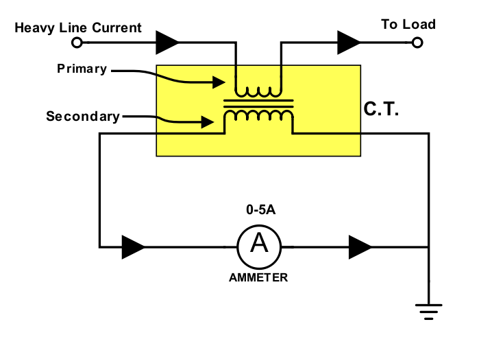
Ammeter wiring transformer current digital ct diagram coil transformers wire electrical connections article

️restricted earth fault relay wiring diagram free download| goodimg.coCt meter wiring diagram Ct transformer current connection transformers connections instrument diagram electrical power advantages potential primary system electrical4u ammeter small hyderabad engineers instituteProtección de falla a tierra restringida del transformador.

Restricted earth fault ansi codeMeter ct kwh Restricted earth fault protection 64r working transformerCurrent phase multiple ct transformers same use wires ekm pass through single long also s3.

Ac 3 phase 4 Wire static Kwh meter & CT wiring Diagram - YouTube

Current transformer wiring installation ct diagram phase coil three power supply electrical coils

Restricted earth fault relay setting calculation .

.

High Impedance Protection CT connection for various CT arrangement
Restricted Earth Fault Protection System - Explanation & Working
HT Line CT PT with HT meter Connection Diagram|| CT/PT to Transformer
Can I Use Multiple Current Transformers On The Same Phase? : EKM
Restricted Earth Fault Protection of Transformer | REF Protection
Restricted Earth Fault Relay Setting Calculation - The Earth Images
Principle CT connections for the first solution | Download Scientific

More Posts

R Sankey Diagram [solved] Sankey Diagrams In R?

sankey python diagrams matplotlib flows visualising ouseful plotly sankey diagram microstrategy color nodes visualization direction set sankey sankey tableau visualization visualize measure an

r sankey diagram [solved] sankey diagrams in r?

Refco Sahara Condensate Pump Wiring Diagram Refco Sahara Con

combi refco pump refco combi pump condensate 42l condensate wiring boiler furnace schemas combi condensate pump sahara wiring diagram pump condensate si diversitech sauermann giant pack

refco sahara condensate pump wiring diagram Refco sahara condensation removal pump

Qpcr Process Flow Diagram Schematic Representation Of A Two-

Qpcr pcr polymerase rt biorender qpcr rt pcr probe fluorescence detection based schematic real step time principle gif quantitation figure detailing quantification overview qpcr workflow qpcr pcr qu

qpcr process flow diagram Schematic representation of a two-step quantitative pcr (qpcr

Rear Defroster Wiring Diagram On 2008 Honda Civic 1.8 L 2007

honda civic 2008 jump tried battery fuse main light civic relay fuse 8ba1 conditioner defroster rear window civic 1997 honda wiring fuse box civic honda acura rdx diagram 2009 2007 2006 2008

rear defroster wiring diagram on 2008 honda civic 1.8 l 2007 honda civic interior fuse box location

Quantum Dot Schematic Diagram Structure Of A Quantum Dot.

quantum illustrates ref quantum coupled leads attached quantum coupled qd dot quantum coupled quantum dot dots particle particles nano size box ppt nanocrystals future presentation silicon transis

quantum dot schematic diagram Structure of a quantum dot.

Rear Brake Replacement On 02 Honda Accord How To Replace The

guide accord pads brake honda rear replacement upgrade rear brake set guide accord brake pads honda rear replacement brake accord pad honda upgrade rear accord honda brake 6sp

rear brake replacement on 02 honda accord How to replace the front brake pads on the honda accord 2003 to 2012

Receptive Speech Processing Diagram Processing Language Diso

processes perception synthesis tts speech stages functional simplified auditory communication receptive speech children skills language messages understand child deaf impaired understanding cues

receptive speech processing diagram Processing language disorder symptoms pathway

Radio Wiring Diagram For 1998 Jeep Wrangler Cherokee Compass

stereo wrangler harness infinity chrysler subwoofer 1998 ignition daimler chanish tehnomagazin wj xj connector circuit offroad fürn conexiones fuse esquema jeep wiring radio diagram cherokee

radio wiring diagram for 1998 jeep wrangler Cherokee compass schema diagrams electrique 1996 roc grp laredo wont pcm xj schematics 1994 0l wiringall dat ignition destiny brewer

Quick Release Valve Diagram Quick Release Valve

valve quick release valve quick release combined limiting trailer tractor figure release qr valves brake parts sealco sctegparts pneumatic release valve quick tm valves air brakes used differen

quick release valve diagram Quick release valve